
Bottle Capping Machine Selection: Caps, Torque and Changeover
How to match a capping machine to the closure and bottle finish: cap types, application vs removal torque, heads, change parts and pre-purchase validation.

What this article covers
This guide helps buyers and engineers define the closure, bottle finish and torque requirement before choosing a capping machine, and plan the checks that confirm the match.
Covered
- Closure and finish types: continuous-thread, snap or press-on, sports caps, ROPP concept
- Application torque versus removal torque
- Capping heads, change parts and validation checks
Not covered
- Closure design or liner material selection
- Induction sealing and tamper-evident band design beyond basic checks
Specifying a bottle without its cap and finish can leave a capper that works on sample closures but fails on your production packs. Match the closure, bottle-finish drawing, supplier torque specification and capping head as one system; application torque is not removal torque.
Scroll horizontally for any hidden columns →
| Input | Evidence to collect | Match to verify |
|---|---|---|
| Cap type | Closure drawing, liner / plug and band | Screw, press-on or roll-on application |
| Bottle finish | Bottle drawing and tolerances | Cap / finish dimensions |
| Torque requirement | Closure supplier specification and test method | Application versus removal range and delay |
| Head | Machine supplier head / insert details | Cap grip, control and per-head checks |
Read this alongside the liquid filling machine selection guide so the filler-to-capper handoff is specified too.
Step 1: Describe the closure system
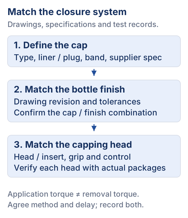
Collect these facts from the cap supplier and the bottle supplier instead of from memory.
Cap and finish types
Scroll horizontally for any hidden columns →
| Type | How it is applied | Points to check |
|---|---|---|
| Continuous-thread screw cap | Rotated onto matching threads until a target torque is reached | Thread and finish compatibility; liner or plug design; tamper-evident band behavior; torque target |
| Snap or press-on cap | Pushed straight down onto the finish; no rotation | Applied force and head travel; finish bead dimensions; how the cap is retained and removed |
| Sports (push-pull) cap | Applied by pressing or by thread, depending on design | Whether the base is threaded or snap-fit; orientation; closure geometry with respect to the head |
| ROPP (roll-on pilfer-proof), concept | Aluminum shell is rolled onto the finish to form threads and a security band | Different machine head (roller head) and finish design; typical for glass; not interchangeable with plastic screw cap heads |
This table is a general overview. Confirm every point against the closure drawing.
Information to put on the project sheet
- Cap diameter, thread style and the exact neck finish designation, with drawings from both suppliers.
- Liner or plug seal design, and any induction seal or foil liner.
- Tamper-evident band, if any.
- Cap feed method: bulk cap hopper and sorter, or pre-oriented chute; cap orientation requirements.
- Heated closures, such as steam-heated caps in some processes.
- Bottle material and wall stiffness, since a flexible container can deform under torque.
- Fill temperature and what happens to the cap and bottle after capping (cooling, pasteurization, refrigeration).
- Required speed, and whether the capper is on the same frame as the filler.
Step 2: Understand application versus removal torque
Application torque is what the machine applies as it tightens the cap. Removal torque is what a person needs to apply to open the closure, usually measured after the package has settled. The two are not equal, and neither reads out the other directly.
According to the supplier documentation reviewed here, the standard closure torque test method developed by the Plastic Bottle Institute (Technical Bulletin PBI 7) rests on a steady correlation between the torque applied to a cap and the torque needed to remove it, and that correlation is used to calibrate a capping machine. The same supplier makes three practical points.
- The cap supplier is the preferred source of the torque specification. Generic charts may not be accurate for a specific cap. In the supplier’s example, one bottle maker specified 27 to 33 in-lb for a 38-430 cap, while a generic chart listed 17 to 26 in-lb for 38 mm caps.
- Specifications are expressed as a range of acceptable results.
- In its worked example, a 28 mm cap on an 8 oz bottle with a manufacturer specification of 13.0 to 17.0 in-lb gave removal torque readings of 8.6 to 8.8 in-lb at 13 in-lb applied and 12.5 in-lb at 17 in-lb applied. This is one supplier’s example and not a general conversion, since the relationship differs for every cap and bottle combination.
ASTM D2063/D2063M describes a method for measuring torque retention of continuous-thread closure systems over time, under defined conditions with a known application torque, using manual torque equipment. Its stated purpose is packaging development and engineering evaluation. It is a useful reference when you ask a supplier how torque retention was assessed.
A closure supplier bulletin adds timing and method points that matter for acceptance:
- Quality checks should be completed in a sequential order on each package.
- For hot-fill packages, the supplier says measurements taken after capping should be completed within one minute; for cold, extended shelf life or aseptic fill, at least ten minutes after capping for accurate removal torque.
- For two-piece lined closures, the supplier uses pull-up, removal torque, security and touch-off together; for linerless plug closures, pull-up and removal torque together.
- If removal torque will be measured by an automated device, a gauge repeatability and reproducibility study should compare it with hand removal before the recommended ranges are adjusted.
These are one supplier’s statements for its own closures. Use them to frame questions and ask your own closure supplier for its equivalent document.
Why can’t you directly measure the torque output of a capping machine?
A capping equipment supplier’s public FAQ explains that motor output is not the torque applied at the closure. A removal tester records opening torque at the agreed delay; use the closure supplier’s method to correlate it with known application settings for this cap and finish, rather than treating either reading as the other.
Step 3: Match the capping head to the closure
The head is the part that touches the cap, and head type follows from the closure.
Scroll horizontally for any hidden columns →
| Head type | Typically used for | Limits and checks |
|---|---|---|
| Chuck (torque-controlled spindle) | Screw caps | Chuck size and insert must match the cap shape; wear affects grip; torque control (clutch, magnetic or servo) must be verifiable |
| Spindle with servo control | Screw caps with data requirements | Allows torque to be recorded per container; confirm what is stored and how it is accessed |
| Snap-on (press) head | Press-on and snap closures | Pressing force and travel; the head must not damage the cap or finish |
| Roller head | ROPP closures | Machine, finish and aluminum shell must be matched to form threads and band correctly |
Ask the supplier how torque is controlled, how it is verified, and how the verification is documented. A machine that holds a setting under one operator may drift under another unless the method is defined.
Step 4: Changeover and change parts
Changeover design is part of the purchase. The OpX Leadership Network’s Total Cost of Ownership material states that fitting changeovers to the manufacturer’s needs is an essential factor in equipment design and acquisition cost, with the manufacturer stating expected rates and needs and the equipment builder providing design capabilities. It also lists set-up, changeover and preventive maintenance among operating costs.
For cappers, change parts commonly include:
- Cap chutes, sorters or cap feed elements.
- Chuck inserts or heads per cap size.
- Star wheels, neck guides and conveyor guides per bottle diameter.
- Height adjustment for different bottle heights.
For each planned format, ask the supplier to list the exact part numbers, the adjustments required, the tools needed, and who performs the changeover. Then ask for a timed changeover during the factory acceptance test with your operators.
What needs project-specific validation
- Run your actual caps and bottles. Use production-representative caps with real liners and bands, and bottles at their real filling temperature or after the real cooling step.
- Torque correlation. Establish the application-to-removal relationship for each cap and bottle combination, using the cap supplier’s method and a defined test interval after capping.
- Torque stability. Confirm the head holds target torque across a defined run and temperature range; check values at the start, middle and end.
- Seal performance. Check seal integrity, liner compression and tamper-evident band behavior against the closure supplier’s criteria.
- Cap handling. Verify orientation, jam rate and damage to the cap, especially for printed or soft caps.
- Interfaces. Confirm handoff from the filler: bottle spacing, neck cleanliness, and what happens when the filler stops.
- Changeover. Time every planned changeover and record parts needed.
- Measurement method. Agree on the torque meter, hand or automated removal, and the sampling plan before FAT.
Torque verification record
Copy one row per sampled package; record cap and bottle lots and the run conditions. Agree the method, delay, sample plan and acceptance criteria with the closure supplier before testing.
Scroll horizontally for any hidden columns →
| Run / sample / lots | Head ID | Application setting / units | Delay after capping / pack temperature | Instrument ID / method | Removal result / units | Criteria reference / outcome |
|---|---|---|---|---|---|---|
Measurement timing: Use the documented delay for the actual closure and process. The cited closure bulletin distinguishes hot-fill and cold/ESL/aseptic measurements; its timing is not a universal rule for other closures. Record both the delay and package temperature so results can be compared.
Takeaway: Use the factory acceptance checklist to define torque tests and records to carry these fields into written acceptance criteria. The OpX Leadership Network’s acceptance test guide aims to resolve the expectation gaps that otherwise lead to confusion for both parties, unbudgeted cost and longer timelines. The OpX Total Cost of Ownership checklist includes a validation step in which the machine is prepared with software and changeover parts and adjustments are noted.
Problems that recur at the capper
- Loose or dropped caps at the filler-capper transition usually point to spacing or neck-wet problems; check liquid on threads.
- Torque that varies between heads points to head-to-head calibration rather than a closure defect. Request per-head verification.
- Cap damage may result from chute design, chuck wear or an over-aggressive setting; check cap supplier tolerances.
- Wet or condensing bottles after cold fill can affect downstream labeling, so connect this decision with the cold and wet bottle labeling checks.
- Material changes in the container can change torque behavior. The materials comparison in the beverage bottle materials guide helps frame which container properties to ask about.
Questions to ask suppliers
- Which closure types and finish designations is the proposed capper designed for, and is it in your documentation or only a verbal statement?
- Which head type is proposed, and how is torque controlled and verified per head?
- What torque range does your documentation state for this cap, and is it based on the cap manufacturer’s specification?
- How should we measure removal torque, at what delay after capping, and by hand or automated device?
- What cap feed system is proposed, and what cap orientation and size ranges does it cover?
- What change parts are required for each of our formats, and what are their lead times and storage needs?
- Does the machine record torque data, and in what format can we retrieve it?
- What are the reject criteria for missing, misplaced or loose caps, and how are rejects removed?
- What is the total changeover procedure and time between our two most different formats?
- What cap and bottle samples do you need from us for a trial, and in what quantity?
- Can the capper be supplied with a trial using our own caps before shipment, and what will the report include?
Include these in the packaging machine RFQ checklist so quotations can be compared line by line.
Summary
Define the cap, the finish and the torque target first. Treat application and removal torque as two linked measurements. Pick the head type from the closure, count changeover parts as part of the machine, and prove the match with your own caps and bottles before you accept it.
Sources and method
This article is based on documentary research of the sources listed. It is not a hands-on equipment test. Supplier statements and editorial judgement are identified in the text.
- ASTM D2063/D2063M: Standard Test Methods for Measurement of Torque Retention for Packages with Continuous Thread Closures Using Non-Automated (Manual) Torque Testing Equipment Supports: that torque retention of continuous-thread closure systems is measured under defined conditions with a known application torque, and that the method is intended for packaging development and engineering evaluation.
- Cap Application Torque Specifications (Torque Guidelines and Measurement) Supports: that the cap supplier is the preferred source of the torque specification, that generic charts may not suit a specific cap, and the supplier's worked example of calibrating application torque against removal torque (PBI 7 method).
- Technical Assistance Bulletin 014: Plastic Closure Quality Checks, Rev. C Supports: using pull-up, removal torque, security and touch-off checks together for lined closures, timing of measurements after capping, and the gauge R&R recommendation for automated removal devices.
- Total Cost of Ownership: Playbook and Checklists Supports: treating changeover options as a design and cost factor, stating expected rates and needs, and including changeover parts in machine validation.
- One Voice for Acceptance Tests (Factory Acceptance Tests; Protocols for Capital Equipment in the CPG Industry) Supports: agreeing acceptance-test protocols between buyer and equipment maker.
- Why You Can't Directly Measure the Torque Output of a Capping Machine Supports: the published FAQ topic and the distinction between motor output, application and removal measurements. Supplier explanation, not our test. Accessed 2026-10-08.
Next reading

How to Choose a Liquid Filling Machine for Food and Beverages
A buyer's framework for choosing a liquid filling machine: project inputs, filling approaches compared, what to validate with samples, and supplier questions.
Read the guide
Labeling Cold and Wet Bottles: Label, Adhesive and Machine Checks
A technical checklist for labeling cold, condensing bottles: container surface, label stock, adhesive and labeler settings, plus a trial on production bottles.
Read the guide
Factory Acceptance Testing for Packaging Equipment: Planning the Checks
Finding defects after shipment can delay installation. Prepare a FAT protocol, representative materials, raw test records and an agreed punch list.
Read the guideMore in Equipment

Liquid Filling Methods Compared: Gravity, Piston and Flowmeter-Based Systems
Compare liquid filling methods by metering principle, product feed and machine structure: gravity, overflow, piston and flowmeter systems and their limits.
Read the guide
Cup Filling and Sealing Machines for Yogurt: A Buyer’s Checklist
A buyer's checklist for yogurt cup filling and sealing machines: stations, cup and lid compatibility, seal checks, cleaning, and questions to put to suppliers.
Read the guide
Food Tray Sealing Machines: How They Work and What to Check
A technical guide to selecting food tray sealers: manual vs inline automation, vacuum MAP gas flush technology, tray and lidding compatibility, and seal integrity validation.
Read the guide